Iranian Classification Society Rules

< Previous | Contents | Next >
Section 8 Tank Containers
801. Application
1. The requirements in this chapter apply to the type approval test and production unit inspection of tank containers for the carriage of liquids and gases with a maximum allowable working pressure
of 0.3 bar (30 kPa, 50 ℃) gauge or above.
2. Tank containers to be used for the carriage of dangerous goods are to be applied by this Rule, in
addition to the requirements of the relevant Government regulations and IMDG Code (international
maritime dangerous goods code) etc.
3. Tank and its associated fittings are to be suitably designed, manufactured and tested in accordance
with the requirements of this chapter, in addition to the requirements of regulations deemed neces- sary by the Society.
802. Materials and Workmanship
Materials and construction used in the tank containers are to be applied by following requirements, in addition to the requirements of Ch 2, 602.
(1) The materials selected for the tank are not to cause a dangerous reaction in contact with the contents. Allowance for corrosion is to be at the discretion of the Society.
(2) Fbeorsuthiteabmleatiesria-1ls0 ℃of ItSoO+c5o0n℃tai.ners, the minimum temperature range over which materials are to
803. Dimensions and Ratings
1. External dimensions, permissible tolerances and ratings for tank containers are to comply with the requirements prescribed in Ch 2, 603. 1. However, internal dimensions are not to be applied.
2. No part of the tank container and its associated fittings or equipment are to project beyond the
overall external dimensions.
804. Design Conditions
1. Design load
(1) The tank container is to be capable of withstanding the loads and loadings specified in Table 2.8, when loads or loadings are removed, container is not to show permanent deformation or abnormality which will make it unsuitable for use.
(2) Each tank container shall be designed to withstand the effects of inertia of the tank contents re- sulting from transport motions. For design purposes, the effects may be taken to be equivalent to loadings of 2 Rg longitudinally, Rg laterally and 2 Rg vertically.
2. Framework
(1) Corner fittings of tank containers are to be applied in accordance with the requirements in Ch 2, 604. 2. In particular, the upper faces of top corner fittings are to protrude above the top of all other components of tank container by a minimum of 6 mm .
(2) Base structure of tank container is to be in accordance with the requirements in Ch 2, 604. 3.
and gooseneck tunnel of tank container is to be in accordance with the requirements in Ch 2, 604. 8. When the tank container is loaded to R, no part of the tank and its associated shell fittings are to project below a plane 25 mm above the bottom faces of the lower corner fittings.
(3) End structure of tank container is to be in accordance with the requirements in Ch 2, 604. 4.
(4) Side structure of tank container is to be in accordance with the requirements in Ch 2, 604. 5.
3. Optional features for framework
(1) In principal, fork-lift pocket is not to be provided in tank containers. However, where fork-lift pocket is required by the Owner is to be at the discretion of the Society.
(2) Where tank containers are provided with the features for handling tank containers by means of grappler arms or similar devices is to be in accordance with the requirements in Ch 2, 604. 9.
(3) Where provided, walkways are to be designed to withstand a loading of 3 kN uniformly dis-
tributed over an any area of 600 mm × 300 mm.
Longitudinal walkways shall have a minimum width of 400 mm.
(4) Where provided, ladders are to be designed to with stand a load of 200 kg on any rung.
![]()
Table 2.8 Load Condition
![]()
Ch 2
Item | Where Applied | Direction | Notes |
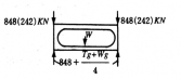
Stacking | Top corner fittings Off-set: ―38 m m longitudinally ―25.4 m m laterally | Other than 1 D and 1 DX contain- ers
1 D and 1 DX containers | 3392 kN (848 kN per top corner fitting) 896 kN (224 kN per top corner fitting) |
Top Lifting | As specified in Ch 6, Table 6.3 | ||
Bottom Lifting | As specified in Ch 6, Table 6.3 | ||
Longitudinal Restraint | As specified in Ch 6, Table 6.3 | ||
Transverse Racking | As specified in Ch 6, Table 6.3 | ||
Longitudinal Racking | As specified in Ch 6, Table 6.3 | ||
Grappler lift (where fitted) | As specified in Ch 6, Table 6.3 | ||
Internal restraint (longitudinal) dynamic | All |
| 0.97W |
Lateral Inertia | Side of barrel wall | Outerwards normal to the side
| Uniformly distributed load 1.0 P |
Internal Pressure | Tank or fluid-tight compartment |
| Minimum 1.5 times of Concentrated ec- centrically applied load design pressure |
Walkway | Walkway (An area of 600 mm × 300 mm Located at the weakest area) | Vertically upwards
| 300 kg |
Ladder | 2 Point on any rung in both end of ladder | Vertically upwards
| 200 kg |
Ch 2
![]()
4. Tank structure
(1) Each tank or tanks are to be firmly secured to structural elements of the tank framework. The tank or tanks are to be capable of being filled and emptied without removal from the framework.
(2) Tanks or tank compartments without vacuum relief devices are to be designed external pressure of at least 0.4 bar (39.2 kPa) above the internal pressure. equipped with vacuum relief valves are to be designed to withstand an external
0.21 bar (20.6 kPa) or greater.
to withstand an However, tanks
over-pressure of
(3) All tank openings except pressure relief devices are to be provided with adequate closures of
capable of being sealed up to prevent accidental escape of the contents, and closure devices are to be capable of being sealed for customs requirements.
(4) Tank nozzles and outlet fittings are to be substantially made and attached to the tank in such a manner as to minimize the risk of breakage. Protective covers or housings are to be employed as necessary.
(5) All tank openings located below the normal liquid level of the contents and fitted with a valve
capable of being operated manually are to be provided with an additional means of closure on the outlet side of valve. Such additional means of closure may be a fluid-tight cap, bolted blank flange or other suitable protection against accidental escape of the contents.
(6) All valves, whether fitted internally or externally, are to be located as close to the tank shell as practicable.
(7) Stop valves with screwed spindles are to be closed by clockwise motion of the hand-wheel.
(8) All tank connections, such as nozzles, outlet fittings and stop valves, are to be clearly marked to indicated their appropriate functions.
5. Pressure relief devices
(1) Each tank or compartment thereof intended to carry non-dangerous cargo is to be fitted with a pressure relief device set to be fully open at a pressure not greater than the tank's test pressure. Such devices are to be connected to the vapour space of the tank and located as near to the top of the tank and as near to the tank's or tank compartment's mid-length as practicable where inspection can be readily conducted.
(2) Above mentioned pressure relief devices are to have a minimum relief capacity of 0.05 ㎥/sec
at standard air [1 bar (100 kPa) 15 ℃] to prevent excessive internal overpressure under
non-emergency conditions.
(3) Tanks, or a compartment thereof, intended for the carriage of dangerous goods are to be pro-
vided with pressure relief devices meeting the relevant regulations to the satisfaction of the competent authority and international convention.
(4) Tank container will be utilized for both dangerous and non-dangerous cargo, the relief devices
are to be set in accordance with (3).
(5).Each pressure relief device is to be plainly and permanently marked with the pressure at which it is set to operate.
(6) A tank container, or a compartment thereof, with external design pressure of less than 0.4 bar (40 kPa) is to be equipped with a vacuum relief device set to relieve at 0.79 bar (79 kPa) abso- sluutree, iesxcneoptt etxhcaetedaedlo.wTehreabvsaocluuutme sreetltienfg dmevaiycebeis uttoilihzeadveparovmidineidmuthmat ththreouegxhtearnreaal doefsi2g8n4㎟pr.es-
6. Manholes
Each tank is to be provided with manholes or other openings of a minimum diameter of 500 mm
to permit internal inspections and repairs.
7. Gauging devices
Gauging devices which may be indirect communication with the contents of tank are not to be made of easily destructible material.
8. Optional features for tank
(1) When insulation is provided, the design and construction are to be such that the insulation will in no way impinge on the requirements in 802. nor interfere with the proper function of the tank fittings.
(2) When heating or refrigeration provisions are required, due consideration is to be given to the safety of the tank and its contents. Suitable safeguards are to be provided to avoid the develop-
![]()
ment of excessive temperature and stresses. Such safeguards are to be easily operable.
Ch 2
![]()
(3) Adequate provision shall be made for the sealing of the tank in accordance with international customs agreements.
805. Type Approval Inspection
1. General
(1) The test items of type approval test for the tank containers are to comply with the followings.
(a) Visual inspection
(b) Dimensional inspection
(c) Mass measurement
(d) Strength tests
(e) Pressure test
(2) The tests and inspections procedures are to be in accordance with the requirements Ch 2, 605.
unless otherwise prescribed in this chapter.
(3) The test procedure may be modified and omitted as appropriate to cater for special features of tank containers.
(4) Where electrical equipment is fitted on the tank container, the installation is to be inspected and
found satisfactory in accordance with the requirements of standards acceptable by the Society.
2. Visual inspection
For insulated tank containers, the visual inspection is the insulating work.
3. Strength tests
(1) Strength tests are to be carried out as specified in
to be conducted prior to commencement of
Table 2.9 after completion of all the work.
However internal restraint (longitudinal) dynamic test(dynamic longitudinal impact test) is to car- ried out as specified in 4.
(2) In the strength tests measurements are to be taken as required in Table 2.9. Additional meas-
urements may be required, where deemed necessary by the Society.
(3) The required loadings in each test are to be applied in such a manner as to allow free de- flection of the container section under test.
(4) The tank container is to be loaded with a suitable fluid to the material to achieve the test load or loading specified. And, when the load at a suitable fluid or dry bulk less than specified in-
ternal load, a supplementary load distributed over the length of tank is to be added to the
container.
(5) Upon completion of the longitudinal or lateral inertia test the tank itself and the tank-to-frame work connection are not to show crack or deformation.
(6) Upon completion of the test, the container is to show neither permanent deformation nor abnor- mality which will make it unsuitable for use.
4. Internal restraint (longitudinal) dynamic tests (dynamic longitudinal impact test)
(1) Test container
Ensure the tank container under test (hereafter referred to as container-under-test) is representa- tive of the tank container design for which conformity confirmation is being sought (design
type). Permitted design variations:
(a) a reduction of 10 % or an increase of 20 % in capacity (resulting from variations in diame- ter and length);
(b) a decrease in maximum gross mass;
(c) an equal or greater thickness, independent of design pressure and temperature;
(d) a change to the grade of material of construction provided that the permitted yield strength meets or exceeds that of the tested container;
(e) a change of location or a modification to nozzles and manways.
(2) Test platform
The test platform shall be
(a) configured so as to allow the container-under-test to be mounted as close as possible to the impacting end;
(b) fitted with four securing devices in good condition;
(c) equipped with a cushioning device for the purpose of achieving a suitable duration of impact.
Ch 2
![]()
Table 2.9 Test Procedures and Measurements
Tests | Procedures and Measurements |
Stacking | Procedure: As specified in Ch 2, 605, Table 2.5. However, internal loading need not provided during test. Measurements: As specified in Ch 2, 605, Table 2.5. |
· Top/Bottom Lifting · Longitudinal Restraint · Transverse Racking · Longitudinal Racking · Grappler Arm | As specified in Ch 2, 605, Table 2.5. |
Internal restraint (longitudinal) dynamic | As specified in Ch 2, 805. 4. |
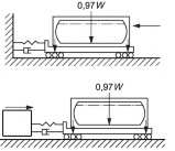
Lateral Inertia | Procedure: Internal load and application: With R-T internal load, the container is to be positioned with its transverse axis vertical and supported by its four bottom corner fittings. The container is to be supported for 5 minutes. Measurements: Diagonal dimension at end section of framework and deflection of tank wall at lower part. |
Walkway | Procedure: Internal load: Nil. Applied loads: 300 kg uniformly distributed over a 600 m m × 300 m m an any area of the walkway. Measurements: Maximum deflection and permanent set of the walkway under test. |
Ladder | Procedure: Internal load: Nil. Applied loads: 200 kg on center of rung. Measurements: Maximum deflection and permanent set of the ladder under test. |
Pressure | Procedure: The Pressure test is to be carried out after all strength test have been completed. The tank container together with its associated pipework and fittings is to be hydrostatically tested to a test pressure not less than 1.5 times the max- imum allowable working pressure or design pressure. The test pressure is to be measured at the top of the tank in its normal position and is to be maintained to enable a complete examination of tank. The test pressure to be maintained for not less than 30 minutes. Relief devices, where fitted, are to be rendered in op- erative or removed. For test procedures other than the above, special consid- eration may be given by the Society. |
(3) Impact creation
(A) The impact may be created by:
(a) the test platform striking a stationary mass, or
(b) the test platform being struck by a moving mass.
(B) When the stationary mass consists of two or more railway vehicles connected together, each railway vehicle shall be equipped with cushioning devices. Free play between the vehicles
shall be eliminated and the brakes on each of the railway vehicles shall be applied.
(4) Measuring/recording system
(A)Unless otherwise specified within this International Standard, the measuring system shall comply with KS R ISO 6487.
(B) The following equipment shall be available for the test:
(a) Two accelerometers with a minimum amplitude range of 200g, a maximum lower fre- quency limit of 1 Hz and a minimum upper frequency limit of 3,000 Hz. Each accel- erometer shall be rigidly attached to the outer end or side face of the two adjacent bot- tom corner fittings closest to the impact source, and aligned so as to measure the accel- eration in the longitudinal axis. The preferred method is to attach each accelerometer to a flat mounting plate by means of bolting and to bond the mounting plates to the corner fittings.
![]()
(b) A method of measuring the impact velocity.
Ch 2
![]()
(c) An analogue-to-digital data acquisition system capable of recording the shock disturbance as an acceleration versus time history at a minimum sampling frequency of 1 000 Hz and incorporating a lowpass anti-aliasing analogue filter with a corner frequency set to a minimum of 200 Hz and a maximum of 20 % of the sampling rate and a minimum roll off rate of 40 dB/octave.
(d) A method of permanently storing in electronic format the acceleration versus time histor- ies so that they can be subsequently retrieved and analysed.
(5) Procedure
(a) The container under test shall be filled, before or after mounting on the test platform, with a quantity of water or any other non-pressurized product to approximately 97 % volumetric
capacity, ensuring that it is not pressurized during the test. However, if for reasons of over- load it is not possible to fill to 97 % of the capacity, then the test mass of the container
(tare and product) shall be as close as possible to R. Measure and record the as-tested pay- load mass.
(b) The container under test shall be placed on the test platform as close as possible to the im- pacting end, with the container end considered to be more vulnerable to impact damage fac- ing the point of impact. All four bottom corners of the container shall be locked in position by means of the corner fittings restraining movement in all directions.
(c)
Create an impact such that for a single impact the as tested SRS at both corner fittings
equals or exceeds the minimum SRS shown in Fig 2.28 at all frequencies within 3 Hz to 100 Hz.(Repeated impacts may be required to achieve this result.)
(d) Examine the container under test for evidence of any faults and record the result.
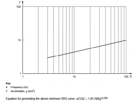
Fig 2.28 Minimum SRS Curve (5 % Damping)
the range
(6) Analysis/processing of data
Analysis and processing of the acceleration time history data obtained from test specified above shall be in accordance with ISO 1496-3, Annex D
(7) Requirements
in (5)
On completion of the test, the tank container shall not show leakage or permanent deformation or abnormality that will render it unsuitable for use, and the dimensional requirements affecting
![]()
handling, securing and interchange shall be satisfied.
Ch 2
![]()
5. Pressure test
(1) The pressure test is to be carried out as specified in Table 2.9 after all strength tests have been completed.
(2) Upon completion of the test, the container is to show no leakage, no permanent deformation or
abnormality which will render it unsuitable for use.
806. Production Unit Inspection for Type-Series Containers
1. The kinds of tests and inspections for production unit of type-series containers, are as specified in Ch 2, 403. and to be carried out in accordance with the requirements in 805. and Ch 2, 605. un- less otherwise specified herewith.
2. For insulated tank containers, the visual inspection is to be conducted prior to commencement of the insulating work.
![]()
3. For production line containers, the pressure test is to be carried out at a reasonable stage during production. In the case of insulated tank containers, the pressure test is to be carried out prior to commencement of the insulating work.
Appendix 2-1
![]()
![]()
![]()